Definition
Models are created to represent reality in a simple way. They offerproblem-solving structure. They help to understand how one can proceed with the imminent problem. And they let you try a lot of solutions. Sincemodels created before system development, we can understandvarious opportunities, problems, options etc. This also leads to a drop in filedevelopment costs. Since time cannot be wasted on product trials and errorswill be ready in a short time. Models also help manage the complexity of the problemtherefore development planning, allocation of resources such as machinery,programmers, testers can be easily done.When modeling is done, most of the system views are defined.Different ideas offer different types of program.For example,The car dashboard and its features are interesting for the car driver. You need to knowwhich button you can press to turn on the interior lights and more. But electrical itemsone does not care about the dashboard in the same way. You're interested inregions behind dashboard. Want to know which buttons to connect toinstruments, gadgets so that when the button is pressed on the driver dashboardyou get the expected performance. The designer is interested in his looks and feeldashboard but not all are involved in what happens behind the panel. Thereforeeveryone looks at the same thing but in different ways.Each idea has a different meaning to that idea. Each idea hasdetails from other views. Data from overone view agrees. This information must be relevant because it isto create views of the same program. This leads to the need for a variety of ideaspresented in various illustrations.
Unified Modeling Language, better known as UML is a visual model language that helps program developers create plans that contain their vision in a common way, easily understood, and provides a way to effectively share and communicate their ideas with others.
Unified Modeling Language (UML) is the language of expression, visualization, architecture, and business modeling and other non-software programs. The UML represents a collection of excellent engineering practices that have proven successful in large-scale modeling. Unified Modeling Language (UML) is the language of precision, construction, visualization, and recording of masterpieces of powerful software programming. First and foremost, Integrated Language Modeling combines the concepts of Booch, OMT, and OOSE. The result is a single, common language, widely used by users of these and other methods. Second, Unified Modeling Language pushes the envelope of what can be done in existing ways. For example, UML authors refer to the modeling of similar systems, which are distributed to ensure that the UML adequately addresses these domains. Third, Unified Modeling Language focuses on standard modeling language, not standard practice. While UML should be used in the context of the process, it is our experience that different organizations and problem areas need different processes. (For example, the process of developing a slightly rolled-up software is interesting, but building wrapped-folding software is very different from building hard-working avionics systems on which life depends.) which provides a personal rendering of these semantics). UML authors are developing a process of development driven by application cases, centric structures, and duplication and ascendancy. The UML defines a modeling language that encompasses social cohesion based on specific concepts of modeling. Allows deviation to be specified according to its extension procedures.Ad Link
UML, a visual modeling language, is not intended to be a visual programming language, in the sense of having all the necessary visual and temporary support to include programming languages. UML is the language for visualizing, articulating, constructing, and recording the art objects of a software that uses a lot of software, but draws a line as it goes to the code. For example, complex branches and joining are best expressed in the language of the learning program. UML has a solid map of the language family of objects so you can get the best of both worlds.
Putting common language at the core of tools and processes. The tools and their functionality are highly dependent on the strict semantic definition and notation, provided by UML. UML defines a semantic metamodel, not a tool interface, storage, or operating model, although this should be close. UML documents include some tips for tool vendors in using the app, but don't look at all that is required. For example, they do not address topics such as graphic color, user navigation, animation, end / launch models, or other features.
Many organizations will use UML as a common language in its art projects, but will use the same types of UML drawings in the context of various processes. The UML deliberately considers intentional, and defining a standard procedure was not the intention of the UML
UML is a mechanism for communication. OOP is the basic building of a UML.
Fields in UML:
How to declare fields in UML
Name:Type
Method in UML
How to declare method in UML:
name( parameter1: Type, parameter2: Type ):returnType
Relation in UML
Things need to work together. Relationships define meaning with links between objects and how links should be translated over time to use the system. There are four types of relationships namely. to depend on, association, dependency, generalization, realization.
Relation:
< ! -- A connection between things -- >
Association ( has a field )
An association is a structural relationship that describes the connection between the two things. It also determines how many things contribute to that relationship. The notation used for the junction is the simplest part of a line or part of a line with arrow.

Association Types:
Aggregation ( is part of )
Aggregation is a special way of association. Specifies the part of the relationship. It creates a binary relationship, which means you can’t include more than two classes. It is also known as Has-a relationship. Specifies direction for the content of another object. In aggregation, the child can be independent of the parent.

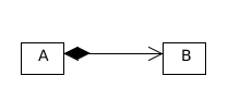
Composition ( is entirely made of )
In a composition relationship, the child is dependent on the parent. It builds a two-way relationship. It is a special case of aggregation. Known as Part-relationship.
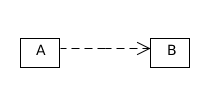
Dependency ( Depends on. Between two or more classes )
Dependence on a semantic relationship in which a change in one object ( independent object) causes a change in the semantics of another object ( dependent object). Text used to trust the line drunk with arrow.
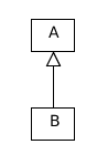
Generalization / Inheritance ( is a. Connect a subclass to its superclass )
Normal practice to form a relationship between a common object (parent or superclass) and
some kind of object (child or subclass). Text used for
generalization is part of a line with a blank triangular arrow head.
The arrow points to the all-encompassing class or use case or package.
Realization
Recognizing the basic relationship between two things in which one clarifies The behavior to be done and the other doing that behavior. i.e. one thing describes one unused bond and another he uses it. This relationship exists in the event of a connection. The text used is a line drawn with a blank triangular block title.

Cardinality (data modeling)
You can set the size by relationship to your model. Most relationships represent the fact that each parent entity or table in a relationship is linked to a certain number of child entity or table conditions.
Relationship:  Left   Right
One-to-one
1	1
One-to-one (optional on one side)
1	0..1 or ?
Many-to-one
1..* or +	1
Many-to-many (optional on both sides)
0..* or *	0..* or *
One-to-many
1	1..* or +
Many-to-many
1..* or +	1..* or +
Example:
A person must have his or her birth certificate [One-to-one]
Someone can get a driver's license [One-to-one (optional on one side)]
Most people can be born in the same area [Many-to-one]
One can have books [Many-to-many (optional on both sides)]
Order contains at least one item [One-to-many]
Students follow a variety of subjects [Many-to-many]
Visibility
The visibility of a class, a method, a variable or a property tells us how this item can be accessed. The most common types of visibility are private and public, but there are actually several other types of visibility in UML
+ public
# protected
- private
~ package ( default )
/ derived
Static ( underlined )
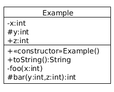
Classdiagram
< ! -- Diagram is a output of UML -- >
ClassName
Attributes
Operations
The name of the class should always begin with a capital letter.
The class should always be in the middle of the starting point.
The class should always be in bold type.
An abstract class name should be written in italics format.
Attributes is the visibility factor.
The middle box contains the class variables.
Operations is the methods.
public class Example {
  private int x;
  protected int y;
  public int z;
  public Example() { ... }
  public String toString() { ... }
  private void foo(int x) { ... }
  protected int bar(int y, int z) { ... }
 }
Use case diagram
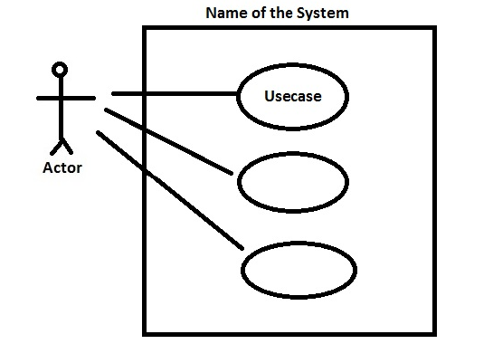
A way to capture the core functionalities of a system.
A use case diagram should represent all interactions with the use case.
If there are too many use cases or actors, then only the essential use cases should be represented.
It captures the dynamic behavior of live system.
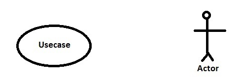
A use case diagram consists of a use case and an actor.
Actors and Use Cases:
Actors are the users of the system. Actors can be human users or other systems. Use cases are the functionalities of the system that users can use.
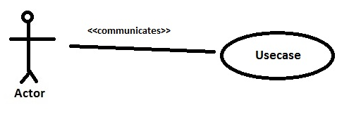
Communicates Relationship:
Communicates is an association between the actor and the use case.
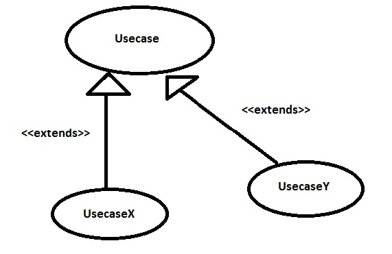
Extends Relationship:
When you want to make functionality optional to use case For example, payments can be made by check, cash or credit card.
Uses Relationship:
Where one use case applies to another use case.
