Use case diagrams consist of 4 objects.
• Actor
• Use case
• System
• PackageAd Link
The items are described in more detail below.
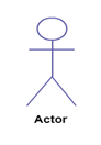
Actor
A character in the case diagram used by any business that plays a role in a given single program. This can be an individual, organization or external system and is usually pulled like the bones shown below.
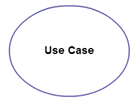
Use Case
The usage case represents an activity or action within the system. It is shaped like an oval and is named after the work.
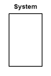
The system
The system is used to define the maximum use case and is drawn as a rectangle. This is an option but is useful if you see large systems. For example, you can create all usage cases and use a program object to describe the size covered by your project. Or you can use it to show different areas covered in different releases.
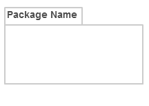
Package
The package is another option that is very useful for intricate designs. Similar to a class diagram, packages are used to combine cases of co-operation. They are drawn as pictured below.